Quantum computers are built on top of single-qubit and 2-qubit operators. In the last two articles, we covered few single-qubit gates, and especially the Hadamard gate which puts a qubit into superposition.
Here, we will explore the 2-qubit operators and more precisely we will look at putting qubits into entanglement with the C-NOT gate.
Classical XOR gate
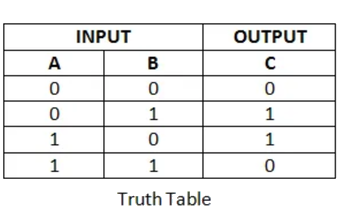
The Controlled-Not gate (CNOT) is analogous to the XOR gate (Exclusive OR) in classical computing. We have already presented in our previous article Introduction to quantum logic gates the XOR gate table truth: it gives a true (1 or HIGH) output when the number of true inputs is odd.
Quantum C-NOT gate
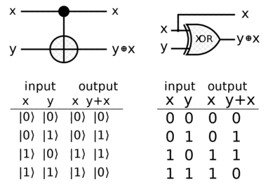
The quantum CNOT gate has two inputs, and thus two outputs. The target input is negated only if the control input is set to 1. If the control input is 0, the gate has no effect. The control qubit is not changed by the gate.
Below is a snapshot of both classical and quantum diagrams. We verify easily that they mirror each other: the quantum Target output column matches the y+x column of the classical XOR gate.
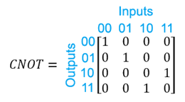
As we already know, each gate/operator can be expressed as a matrix. As the C-NOT gate takes two qubits as inputs and two qubits as output it will be a 4x4 matrix.
There is a useful technique to transform a truth table to a matrix. starting at row 0 column 0, you label the columns and rows consecutively in binary, from 00 to 11 for example. You then place a 1 in a cell if the input maps to the output; 0 otherwise.
For example, in our case, as |11> maps to |10> we set the matrix's value of 4th line, 3th column to 1.
That's it, you're left with a matrix for your gate.
Let's try to apply the CNOT-gate by example to the |00> state, by multiplying the CNOT matrix to the basis state vector

We observe that it is the expected result ;-)
If we now try to apply the CNOT gate to the |10> state, by definition as the control qubit is |1>, the second qubit should be flipped from |0> to |1>. Let's observe it:

As expected, we get |11>.
Remark 1: More generally, the inputs are allowed to be a linear superposition of {|0>,|1 >}. The CNOT gate transforms the quantum state:
a|00> +b|01 +c|10 +d|11>
into
a|00> +b|01> +c|11> +d|10>
Remark 2: The first experimental realization of a CNOT gate was accomplished in 1995 with a single Beryllium ion.
Bell State
Let's try now to prepare a two-qubit system by example in |00> state, and then:
- apply the Hadamard gate to the first one so we get a 50/50 superposition state as detailed in Introduction to quantum logic gates
- then apply the C-NOT gate with the second qubit |0> acting as the control qubit
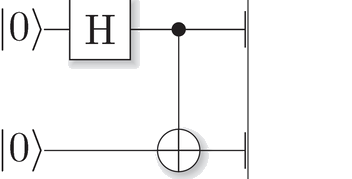
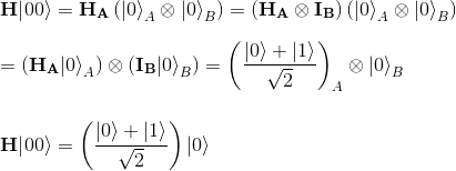
In the first step, the Hadamard gate transforms |00> in the superposition state (H|0>)|0> as per below:
This will then act as a control input to the CNOT gate, which only inverts the target (the second qubit) when the control (the first qubit) is 1. Thus, the CNOT gate transforms the second qubit as follows:

In the first line, we used linearity, and in the second line we used the definition of the CNOT gate.
The result is one entangled state, the one we have taken in example in our articles Expectation value of an entangled state and Correlation in entangled state

Remark 1: we remind here what this entanglement means: the qubit held by Alice (subscript "A") can be 0 as well as 1. If Alice measured her qubit in the standard basis, the outcome would be perfectly random, either possibility 0 or 1 having probability 1/2. But if Bob (subscript "B") then measured his qubit, the outcome would be the same as the one Alice got. So, if Bob measured, he would also get a random outcome on first sight, but if Alice and Bob communicated, they would find out that, although their outcomes seemed random, they are perfectly correlated.
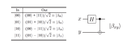
Remark 2: this state represents one of the four maximally entangled two-qubit Bell states. The different ways to create different Bell states |β00>, |β01>, |β10>, |β11> is to apply the precedent two gates to respectively each initial two qubit input |00>, |01>, |10> and |11>.
Let's detail the creation of the three remaining Bell states

Applying the CNOT gate to this state gives:

Let's focus on the Bell state |β10> which takes |10> as input state:
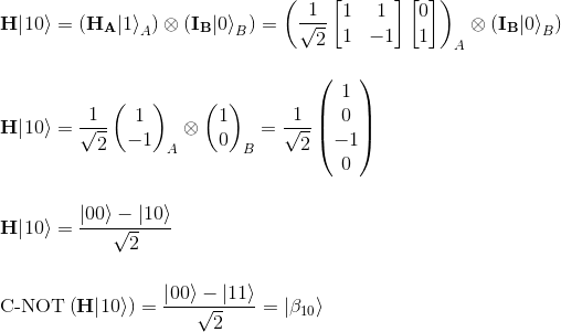
Finally let's consider the last Bell state |β11> which takes |11> as input state:
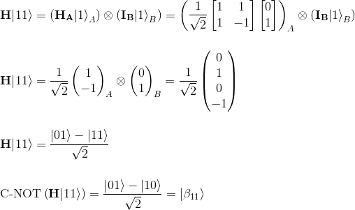
Finally below are the different ways to create different Bell states:
